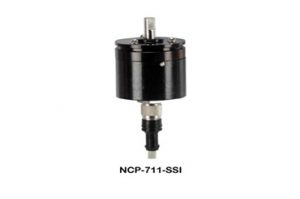
10 Bit Absolute Analogue Encoder
Model: NCP-711-SSIE (Serial Synchronous Encoder)
Absolute Analogue Servo Encoder is operating on Hall’s effect principle. There is no metallic moving wiper
contacting to element and hence no wear and tear or sliding electrical noise. Shaft is rotating endlessly in
double ball bearings giving very smooth movement. It has excellent mechanical response with no hysteries
in the output. The Sensor and electronic circuits are enclosed in anodized aluminum housing with IP-65
protection, It is ideal for harsh environment applications.
Features
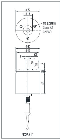
- 50 mm Diameter Black Aluminum Anodised housing
- Double Ball Bearings
- 8 mm Stainless Steel ‘D’ cut Shaft
- Servo Mounting or three M3 Screws at 32mm PCD
- Low operating torque
- Connector with cable
Specifications
| Angle of Rotation | 0~360° Clockwise rotation (Endless), can be factory programmed for double ball bearings giving very smooth movement. It has excellent mechanical response with no hystersis 45°,90°, 180° and Counter Clockwise Rotation (CCW) |
| Auxiliary Supply (Vss) | 9VDC to 30VDC±10%, 25mA max |
| Output | SSI and 5VDC |
| Total Independent linearity | ≤0.7° (with respect to best line fit and over full temperature range) for V & mA output |
| Resolution | 10 bit (0.35°) over 360° for 360° range 11 bit (0.176°) over 180° for 180° range 12 bit (0.088°) over 90° for 90° range 12 bit (0.088°) over 45° for 45° range |
| External Magnetic Field Effect | Small effect due to Differential measuring technique & sensor conditioning circuitry. (It is desirable to mount encoder away from strong magnetic field, at least 100mm |
| Maximum Angular Shaft Speed | 3000RPM. Number of samples per revolution decreases as the speed of rotation increases. Accuracy of output is not affected by Speed |
| Operating Temperature Range | 0°~70°C |
| Temperature Compensation | No external compensation required |
| Insulation Resistance | 2MΩ min. @ 500VDC |
| H.V. Test | No damage for 1 min at 250VAC |
| Rotational life | 100 million |
| Protection Class | IP-65 |
Wiring Colour Code
| Red | Vs – 24VDC Supply |
| Black | Gnd – Circuit Ground |
| White | V – 0 to 10VDC, O/P corresponds to 0° to 360° for V & S |
| Blue | Io – 4 to 20mA, O/P corresponds to 0° to 360° for V & S |
| Brown | CS – Chip Select, Normally Heigh, Active Low, Schmitt Trigger Input with Pull-Up Resistor of ~50KΩ |
| Grey | CLK – Clock, Normally High, clock input of SSI, Schmitt Trigger input, Frequency: >0 to1MHz |
| Green | DO – Data Output of SSI |
Functional Description
When CS is at logic low (active), DO will change to High from High Impedance state. After 500ns (CLKFE) time data is latched into shift register with first falling edge of CLK. With subsequent rising edge of CLK pulse, one data bit shifts out at DO. Word contains 16 bit. First 10 bits are angle information D(9:0). D9 is MSB and D0 is LSB of angle information.
Subsequent 6 bits are for system information viz.:
OCF – Offset Compensation Finished; OC algorithm has finished and data is valid if logic High,
COF – Cordic Overflow; Logic High indicates an out of range error in the cordic part, data D(9:0) is invalid.
Send the encoder to factory.
LIN – LINearity Alarm; Field generates a critical output linearity when logic High, data D(9:0) may
still be used but may contain invalid data. Send the encoder to factory.
MagInc – Magnitude Increase, field intensity is increasing, check the external magnetic disturbance.
MagDec – Magnitude Decrease, field intensity is decreasing, check the external magnetic disturbance.
Both above at logic High indicates magnetic field strength is below or above the required limit.
Check for external magnetic influence. If not i.e. field strength is below the desired level, send the encoder
to factory.
Even Parity – bit for transmission error detection of bits 1 to 15 (D9…D0, OCF, COF, LIN, MagInc, DecMag).
Other Functionality:
Sample Rate:
Sampling Rate, n = 60/(RPM x 384μs).
e.g. RPM = 60, then n = 60/(60 x 384 x 10-6) = 2604 samples/second.
MagRngn – Magnet Field Magnitude Range Warning (Optional), it is combination of MagInc and MagDec.
Active Low via open drain output, requires an external pull-up resistor. If the magnetic field is in range,
this output is turned off (logic High).
Diasy Chain: It allows connection of several encoder in series, while still keeping one input for data
transfer in μP (Optional).
Applications
- Automation,
- Test and Measuring Instruments,
- Crane, Angle Measurement,
- Robotics & many more.
Options
NC711-SSI (Serial Synchronous Interface)
SSI/45°, CW or CCW
SSI/90°, CW or CCW
SSI/180°, CW or CCW
SSI/360°, CW or CCW – (Standard SSI)
Dimensional Diagram
Note: We reserve the right to make any kind of design, specifications or functional modification at any moment without prior notice
- Date: December 28, 2019
- Category: POTENTIOMETERS